How We Work

It is our goal to provide a clear understanding of what we at Total Tool Solutions need to provide you and your customers with the most comprehensive proposals and ergonomic systems possible. We have compiled a presentation that consist of six parts, an overview, material handling terminology, a description of the components of an ergonomic system, product descriptions and where they are best applied. This also includes an application data sheet, as well as system layout templates.

As we progress through this presentation your input with any questions or suggestions on how we may better serve you and your customers are greatly appreciated. The information gathering phase of any project is the most crucial part of ensuring success, as with anything “Quality In, Quality Out”.

We greatly appreciate the opportunity to work with you in meeting the ergonomic and material handling needs of your customers. Our goal is to work as partners to maintain open lines of communication to ensure a smooth flow of information. These goals are the keys to expanding both of our company’s opportunities with the existing and sure to be new customer base.

Anatomy of an Ergonomic System

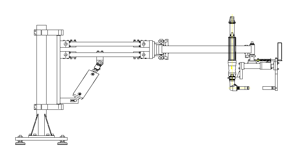
In nearly all ergonomic systems, whether a tool or material handling application the solution will be made up of four parts. The lift, the suspension, the tool (end effector), and the controls, all of these components will vary widely from application to application. The lifts are available in many forms and configurations; the most common used are:

The suspension can consist of an overhead bridge and rail system; the bridge can be either single or dual girder. The runways in most instances will be a dual rail set up with or

without a bridge, however there are instances that a single runway would be used such a tool rail or material handling application where the pick and place are in line. Other suspension options include floor, bench top, column or ceiling mounting.

The tool or also referred to as an end-effector can be as simple as a j-hook type for material handling or single compliant pinch clamp type for torque tool holding. This can also be the most complicated part of an application, using clamping, vacuum, and magnets. The end-effector provide tilting, rotation and manipulation of tools and materials. These attributes of an end-effector are the key to reducing the fatigue and injuries to operators that are associated with most assembly or material handling applications. In many applications the end effector will be specifically designed to fit the application at hand.

The controls range from the tensioning of a spring on a spring balancer, or single balancer regulator used in many nut-runner applications. Or can be as complicated as multiple load balances, and incorporate tilts, rotates and can be sequenced. These systems can either be pneumatic or PLC controlled, they can also interface with the controllers used with most DC nut-runner applications. This portion of a system like the end-effector in many applications will be designed specifically to fit a dedicated application.

Ergonomic Material Handling Terminology

This is a device with a vertical column that supports two horizontal beams with a pneumatic cylinder arrangement that offsets the load of tooling and part loads attached to the end plate of the horizontal members. Arms are most commonly used in torque absorbing or material handling applications.
The horizontal segment at the top of a vertical bail to reach the center of gravity of the load being lifted.
A Two-Position Control is used to automatically sense the presence of a part on the handling fixture and shift the balancer into the presence of a part on the handling fixture and shift the balancer into the loaded position. This control is useful on jobs where a single weight is constantly being handled. If two weights are being handled a high/low selector switch will be used. A push-button is installed on the handling fixture to release the load. The 2 P/S can be used with mechanical or vacuum handling fixtures.
The use of an air cylinder to activate the linkage or clamping mechanism of a handling fixture. This cylinder is tied in with the interlock valve (see interlock valve) and has an open/close control mounted on the handling fixture.

A Mechanical means of attaching the cable of the balancer to the handling fixture.  See “C” Bail.

This is the release valve for a vacuum fixture. Rather than shutting air off to the vacuum cups the blow off control blows air into the circuit and “pops” the cups from the surface of the part. This leads to longer cup life, and faster cycle times.
This is a horizontal beam with end trucks attached at either end, and can be either an enclosed or I-beam type track. This can be a single or dual girder bridge, the end trucks are suspended from a dual runway system that provides for “X” and “Y” movement that allows for complete coverage of a work area. These bridges are used for supporting the carriage of a lifting device on an ergonomic system and can be a cable balancer, arm, torque tube/vertical balancer or other lifting device.
A purchased item, a Bullard hook is used at the end of the cable to attach to the handling fixture. This item is assembled to the cable with two cable clamps and a cable thimble.
This is a component that is used to support the lifting device of an ergonomic system, it has trolleys attached in the corners and can be two or four trolley type. These trolleys can be I-beam or enclosed track type, the construction of a carriage can be a bolt together type or weldment.
The amount of time an operator has to perform his handling operation. This information is important in designing a handling system. We do not want to increase the time cycle; likewise we do not want to commit to unrealistic times.
A mechanical stop to limit the rotation of a part in the horizontal vertical position. This feature can be spring actuated with a lever handle or air cylinder operated. Stops can be positioned at most any point of rotation.
Dunnage is the cavity or nesting place for a part to be placed into, or removed from. Dunnage can be the removable rails usually with urethane separators on the side and bottom of racks, as used in the automotive industry. It can also be the plastic, cardboard, or styrofoam inserts used in shipping cartons. Dunnage should be looked at when reviewing an application; the area around the part and the dunnage is a critical area for handling fixture obstructions.
End effector is another term for a handling fixture. Robots have end effectors, and the terminology has carried over into our business.
End trucks are the wheel assemblies supporting the bridge crane to the runways. End trucks allow the bridge to move along the runways smoothly and with little effort.
The total amount of space from the floor to the lowest obstruction in the ceiling above the work cells. This dimension could be to an existing rail, air ducts, light, or to a building truss. The second headroom term used is the distance from the lowest obstruction to the bottom of the balancer. This stack up of dimensions determines the working area for the handling system.
Vacuum is measured in inches of mercury. All vacuum applications should draw over 18 inches of mercury, to be considered safe.
This valve interlocks the balancer with the air circuitry of the handling fixture. An air pressure setting is set for the weight of the empty handling fixture, once the pressure in the balancer exceeds this setting the Interlock valve shifts and will not allow the release circuit to operate. The operator cannot release the part in error while being transferred. The Interlock is standard on all vacuum and air cylinder operated handling fixtures.
The J-Hook is the simplest form of lifting, J-Hooks are most commonly used where a round cylindrical shape can be accessed and cradled, these are generally supported by a cable style balancer.
A pivoting rail hung over a work cell. A balancer/hoist is mounted to the jibs’ rail. Jibs can be mounted from the floor, ceiling, or to an existing column.
Jog controls are used to start and stop air cylinder movement while clamping to a part. Using this optional control the operator does not have to use the fixture at its full open position when empty. Use this control when handling a wide variety of sizes to clamp.
A means of securing the load to the handling fixture. This clamping action could be manually operated or air cylinder operated (see air cylinder clamp). The three basic means of addressing a lifting task are mechanical clamps, vacuum, or cradling the load.
This valve senses the presence of a part in place and located properly in the handling fixture. Using this valve, air cylinders can be activated, vacuum turned on, or the 2 P/S valve actuated. See 2 P/S.
Rotating a part using the aid of an air cylinder, rotary actuator, or air motor. The ideal means of rotation is using gravity, when this is not a practical method then a power assist is used.
The reeve block is used to increase the lifting capacity of a balancer. Rather than the cable ending at the load hook the cable goes through the reeve blocks pulley and back up to the balancer. This will double the capacity but reduce the distance of lift by half. Available on all units over 200 lb. Capacity.
Parallel rail that is hung over a work station. Runways provide the track for bridge cranes, and carriages. Runways can be standard I beam or patented rails.
A shifting center of gravity will allow the empty or loaded fixture to remain perpendicular to the pick up and set down angle. A shifting center of gravity is used mostly on applications requiring heavy handling fixtures and the use of “C bail.”
A vertical shaft and bearing arrangement with a cylinder used to support the load of a tool or nut-runner application. This device is used to transfer the torque associated with power tool securing applications from the operator to the handling device, and to minimize operator fatigue and injury.
A powered drive attached to a bridge crane, or bridge to move it along a set of overhead rails. In most applications the tractor drive is powered by an air motor or electric with a running wheel that makes contact with the surface of the overhead rail. A forward/reverse control valve is attached to the handling fixture.
Trolleys are the wheel assemblies that the end trucks are made of, and what connect the balancers to the bridges. Trolley wheels are available in several materials for both enclosed and I beam styled rails.
Air flowing through the venturi creates a vacuum, thus air is removed from the sealed vacuum cups and all hose lines. The ideal draw of vacuum is usually from 18 inches of mercury up to 26 inches. This valve may also be called a vacuum generator.
A vertical shaft and bearing arrangement with a cylinder used to support the load of an end-effector and part. These units are most commonly used in material handling applications where the lifting loads exceed acceptable ergonomic standards.
Scroll to Top